Choosing the best solar pole mount starts with the site, not the product brochure. A pole mount must carry panel weight, resist wind, manage snow, and protect electrical connections. It must also suit soil conditions, shading patterns, access needs, and local structural requirements.
The market is growing quickly. IRENA reported 345.5 gigawatts of new solar capacity worldwide in 2023. This expansion increases demand for durable mounting systems. However, capacity statistics do not prove that one mount design fits every property. That assumption is convenient, and sometimes wrong.
Solar engineer Ryan Mayfield emphasizes a practical principle: “The racking must match the site, the array, and the installer’s experience.” His point deserves attention. A tall steel pole may improve winter exposure, but it can face stronger wind forces. A low pole can simplify maintenance, yet nearby trees may create morning shadows. Small decisions matter.
The U.S. Department of Energy recommends evaluating orientation, tilt, shading, and structural safety before installation. Standards such as ASCE 7 and UL 2703 also support disciplined engineering and equipment selection. Buyers should request load calculations, foundation details, corrosion protection, warranty terms, and installation references.
There is no universal winner.
The best solar pole mount balances energy production, soil stability, maintenance access, cost, and long-term reliability. It may be a fixed mount, an adjustable design, or a tracking system. A careful comparison should expose trade-offs rather than hide them. In the following guide, each option will be examined through measurable performance, field practicality, and credible engineering evidence.
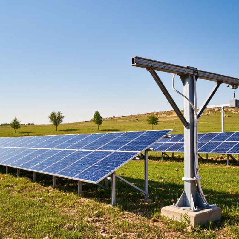
A solar pole mount is a steel or aluminum structure that supports photovoltaic panels above the ground. Instead of attaching panels to a roof, installers secure the frame to one or more buried poles. The poles transfer panel weight and wind pressure into compacted soil or concrete. Many systems use a fixed angle, while adjustable designs can follow seasonal sun changes. This setup can improve airflow and simplify cleaning and inspections.
In practice, installation begins with a careful site survey. A qualified technician checks shading, soil strength, drainage, and underground utilities. The pole must reach a suitable depth for local wind conditions, not just panel weight. Installers then clamp panels to rails and route cables through protected conduit. Grounding and correctly rated disconnects remain essential. Field inspections often reveal small layout errors that complicate later maintenance. A tilted frame may look efficient, yet poor drainage can leave mud around its base. That detail is easy to miss. The best solar pole mount is the one matched to the site, panel arrangement, and local conditions.
What Is the Best Solar Pole Mount?
Solar pole mounts come in several forms, and the best option depends on the site. A top-of-pole mount supports panels above the pole. It offers strong visibility and simple row spacing. This design suits open ground with limited shading. A side-of-pole mount attaches panels beside the pole. It works well near fences, buildings, or narrow service areas. However, nearby objects may cast shadows across the lower modules. That detail is easy to miss.
Fixed-angle mounts hold panels at one permanent tilt. They usually need less maintenance and resist movement during strong winds. Adjustable-tilt mounts allow seasonal angle changes. They can improve energy capture, but someone must safely access the adjustment points. Single-axis trackers follow the sun across one direction. Dual-axis trackers adjust both direction and tilt. These systems may produce more electricity, yet they add motors, controls, and maintenance needs. Multi-pole structures distribute larger panel arrays across several posts. They require careful soil testing and accurate alignment.
Site experience matters here. I have seen clean-looking layouts struggle because of poor drainage or underestimated wind loads. A stronger mount is not automatically better. The pole diameter, foundation depth, local weather, panel weight, and maintenance access must work together. I would also check winter shadows, even when summer sunlight looks excellent. Small oversights can reduce output for years.
Solar pole mounts are commonly selected by the number of photovoltaic modules they can support. Side-of-pole mounts are suited to small installations, top-of-pole mounts generally support small to medium arrays, and multi-pole systems are used for larger ground-mounted arrays. The best option depends on array size, wind and snow loads, soil conditions, tilt requirements, and available space.
What Is the Best Solar Pole Mount?
How to Choose the Best Solar Pole Mount for Your Site
Choosing the best solar pole mount begins with the site, not the product. Measure the available sunlight throughout the year. Nearby trees can cast long winter shadows. Even partial shading may reduce system output.
Check the soil before selecting the pole size. Loose, sandy ground may require deeper foundations or additional engineering. Rocky soil can make installation slower and more expensive. Wind and snow loads also matter. A qualified professional should verify structural calculations and local permit requirements. Do not rely on appearance alone.
Orientation affects energy production. In many locations, panels perform well when facing the strongest annual sun position. However, roof lines, trees, and seasonal shadows can change that choice. Tilt adjustment may improve production, but it can increase wind pressure. That trade-off deserves careful review.
Access is another practical concern. Leave enough clearance for mowing, inspection, and cleaning. Use corrosion-resistant hardware, especially near coastal air or agricultural chemicals. Protect cables from animals, water, and sharp metal edges. Small details matter.
A field inspection may uncover problems that photographs miss. I would rather see a slightly higher installation cost than a weak foundation or difficult repair. Still, estimates are not perfect. Soil conditions can change within a few meters. Recheck measurements before ordering materials, and ask an engineer to review unusual sites.
What Is the Best Solar Pole Mount? What Are the Key Installation Requirements?
The best solar pole mount depends on soil, wind exposure, panel weight, and access for maintenance. A reliable installation begins with a site assessment, not a product choice. Check the ground for rock, loose fill, drainage problems, and buried utilities. The pole must remain stable during strong gusts. In many locations, local building rules may require stamped structural calculations or inspection.
Use corrosion-resistant hardware suited to the local climate. Coastal air, heavy snow, and frequent rain can change material requirements. Set the foundation below the area affected by frost, where applicable. Concrete must cure properly before the array is attached. Follow the mount’s torque specifications carefully. Loose bolts can create movement, while overtightening may damage components. The panel angle should support energy production without creating unnecessary wind load. Leave enough clearance for wiring, cleaning, and seasonal vegetation.
Tips: Measure twice. Photograph the foundation before covering it. Use conduit to protect cables from sunlight, moisture, animals, and accidental contact. Keep grounding connections clean and continuous. An experienced installer can identify structural weaknesses that a quick visual check misses. I have found that small alignment errors become obvious later, especially when several panels must share one frame. Recheck the pole after the first severe weather event. Some assumptions fail in the field.
| Evaluation Dimension | Recommended Specification or Practice | Why It Matters | Installation Verification |
|---|---|---|---|
| Best Overall Mount Type | A fixed-tilt, galvanized-steel pole mount with an engineered foundation is the most practical choice for many ground-mounted residential and small commercial systems. | It provides strong structural support, relatively simple installation, low maintenance, and no moving parts. | Confirm that the design is suitable for the panel quantity, local soil, wind exposure, snow conditions, and applicable building codes. |
| Pole Material | Use hot-dip galvanized structural steel or another corrosion-resistant material rated for outdoor exposure. | Outdoor steel is exposed to moisture, soil contact, temperature changes, and potentially corrosive environments. | Check the coating specification, steel grade, fastener compatibility, and whether cut or drilled surfaces require corrosion protection. |
| Foundation Type | Use a reinforced concrete foundation or an engineered driven-pile solution, depending on soil conditions and local approval requirements. | The foundation transfers wind, snow, equipment, and seismic loads safely into the ground. | Verify foundation diameter, depth, reinforcement, concrete strength, curing time, and minimum separation from property lines and underground utilities. |
| Soil Assessment | Evaluate soil bearing capacity, frost depth, drainage, slope, groundwater, and the presence of rock or expansive soil before finalizing the design. | Soil conditions directly affect foundation size, pole embedment, settlement risk, and long-term stability. | Use a qualified site assessment or geotechnical recommendation when soil conditions are uncertain or loads are high. |
| Wind Design | Size the pole, rails, connections, and foundation for the site-specific basic wind speed, exposure category, topography, and panel array geometry. | Solar modules act as large surfaces that can create significant uplift, lateral, and overturning forces. | Obtain the applicable wind criteria from the local code authority and confirm that the engineering calculations cover the complete assembly. |
| Snow and Ice Loads | Include the local ground and roof snow-load requirements, panel tilt, drifting, and potential ice accumulation in the structural design. | Snow loads can add substantial weight and bending forces to modules, rails, poles, and foundations. | Check the permitted module loading, rail span, fastener capacity, and whether snow sliding could create a safety hazard. |
| Tilt Angle | Use a fixed tilt selected for the site latitude, seasonal energy goals, roofline or landscape constraints, and snow-shedding needs. | Tilt affects annual energy production, row shading, wind loading, and snow accumulation. | Confirm the tilt with the system designer; do not change the angle without checking structural clearance and load effects. |
| Azimuth and Orientation | In the Northern Hemisphere, a generally south-facing array often provides strong annual production; other orientations may be suitable when site conditions require them. | Orientation influences solar exposure, energy yield, and morning or afternoon production. | Check for shading from trees, buildings, utility poles, and terrain throughout the year rather than relying only on a single site visit. |
| Module Clearance | Maintain the clearance specified by the module and mounting-system instructions, with sufficient space for drainage, airflow, wiring, and maintenance. | Proper clearance helps prevent water accumulation, reduces heat buildup, and protects cables and connectors. | Verify clamp locations, rail spans, underside clearance, and that no module frame is drilled or modified unless explicitly permitted. |
| Array Height | Set the lowest edge high enough to avoid routine vegetation, splashback, snow contact, and accidental impact while keeping maintenance access practical. | Excessively low arrays are vulnerable to debris and vegetation; excessively high arrays increase wind moment and installation complexity. | Confirm ground clearance, access requirements, visibility restrictions, and local rules for detached structures. |
| Electrical Grounding and Bonding | Bond exposed metal components and connect the system to the grounding electrode system in accordance with the applicable electrical code. | Grounding and bonding help reduce shock hazards and provide a controlled path for fault current. | Use listed grounding hardware, verify continuity across rails and structural members, and document the grounding electrode connection. |
| Cable Management | Route cables away from sharp edges, standing water, moving parts, and direct contact with the ground; use outdoor-rated clips and conduit where required. | Good cable management prevents abrasion, UV damage, connector stress, and ground faults. | Confirm connector compatibility, drip loops, bend radius, conduit support, and separation of power and communication wiring. |
| Lightning and Surge Protection | Evaluate the need for surge protective devices and lightning protection based on local risk, system voltage, building connections, and electrical-code requirements. | Surges can damage modules, inverters, monitoring equipment, and connected building equipment. | Coordinate surge protection with the electrical design and verify that bonding paths are short, secure, and code-compliant. |
| Corrosion Control | Use compatible metals, corrosion-resistant fasteners, sealed electrical enclosures, and appropriate isolation between dissimilar metals. | Galvanic corrosion and moisture ingress can weaken structural connections and shorten equipment life. | Inspect fasteners, washers, coatings, drainage points, and any locations where aluminum, galvanized steel, stainless steel, or copper meet. |
| Load Path and Connections | Every connection—from module clamps through rails, brackets, pole, and foundation—must be designed as part of one continuous structural load path. | Weak or incompatible connections can fail even when the individual components appear adequately sized. | Use specified bolt grades, torque values, washers, hole sizes, and connection details; record torque checks during installation. |
| Shading and Row Spacing | Provide enough spacing and elevation to limit inter-row shading during the target production period, especially around the winter sun angle. | Shading can reduce energy output and may affect multiple modules when they share electrical strings. | Review a site-specific shade study and confirm that future vegetation growth has been considered. |
| Permits and Inspection | Obtain required planning, structural, electrical, and utility approvals before construction. | Permits confirm that the installation meets local safety, zoning, fire-access, and grid-connection requirements. | Keep stamped drawings, equipment specifications, inspection records, and utility approval documents with the project file. |
| Maintenance Access | Provide safe access for module cleaning, visual inspection, vegetation control, wiring checks, and replacement of electrical equipment. | Accessible equipment is easier and safer to maintain over the system’s service life. | Confirm walking clearance, working space around disconnects and inverters, stable ground conditions, and safe ladder or lift access. |
| When to Use a Different Mount | Consider a multi-pole, helical-pile, ballast, or tracking system when array size, soil conditions, land use, or energy objectives justify the added design complexity. | No single pole-mount configuration is optimal for every site; structural and economic conditions determine the best solution. | Compare lifecycle cost, installation equipment, maintenance, permitting, land disturbance, and expected energy gain before selecting an alternative. |
| Final Selection Rule | Choose the mount that satisfies structural, electrical, environmental, access, and permitting requirements—not simply the mount with the lowest purchase price. | System reliability depends on the complete design and installation, not on the mounting frame alone. | Have the final design reviewed by a qualified solar professional or licensed engineer where required by local regulations. |
A solar pole mount deserves more than a quick visual check. Inspect the pole after heavy rain, strong wind, or ground movement. Look for leaning, cracked concrete, rust stains, loose bolts, and cable abrasion. A clean panel can still hide a loose clamp. Use a calibrated torque wrench when checking accessible fasteners, following the installer’s specifications. Do not guess the torque.
NREL’s photovoltaic degradation analysis reports a median module degradation rate near 0.5% per year. A sudden production drop usually signals a fault, shading change, wiring issue, or inverter problem. Compare monthly energy against weather-adjusted expectations, not one sunny afternoon. IEC 62446-1 recommends documented verification and electrical testing during system evaluation. Record insulation resistance, polarity, grounding continuity, and open-circuit voltage through qualified personnel.
The foundation needs special attention. Measure visible settlement and check whether water collects around the pole. Poor drainage can weaken soil and accelerate corrosion. NREL’s PV Operations and Maintenance Best Practices recommends planned inspections, maintenance records, and clear corrective actions. Keep photographs, torque readings, test results, and repair dates together. That history supports warranty reviews and future engineering decisions.
A practical review should also reconsider the original wind and snow assumptions. Local conditions may have changed. The first design may not remain perfect.