Choosing among the top solar pole mount systems requires more than comparing prices or panel capacity. Global buyers must examine structural strength, installation methods, material quality, and long-term service support. A system that performs well in a dry inland region may struggle near saltwater or under heavy snow. Local conditions matter.
This guide examines solar pole mount options through practical, measurable criteria. These include pole diameter, steel or aluminum grade, coating thickness, tilt adjustment, foundation design, and cable protection. We also consider wind exposure, soil stability, drainage, and access for maintenance. Small details matter. A loose fastener or poorly sealed cable entry can reduce reliability over time.
Experienced installers often begin with a site survey, not a product brochure. They check wind and snow loads, shading, ground conditions, and available equipment. Buyers should also request engineering documents, installation instructions, warranty terms, and evidence of quality testing. Regional building requirements may differ, so professional review remains essential.
There is no universal best system. That assumption fails. A fixed mount may suit a simple rural installation, while an adjustable design can improve seasonal positioning. However, adjustment adds parts, labor, and possible maintenance points. This comparison aims to clarify those trade-offs without overstating performance. Some manufacturers provide excellent hardware but limited support outside their home market. Others offer responsive service but fewer configuration choices. Careful buyers should compare both. The strongest decision balances safety, energy yield, installation practicality, and dependable support for the system’s full operating life.
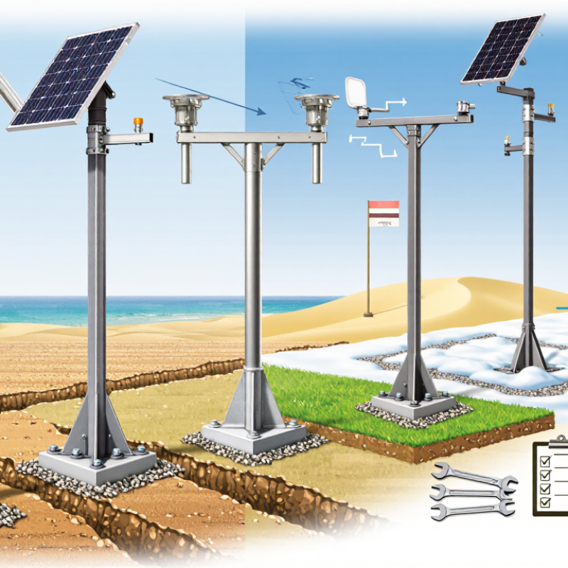
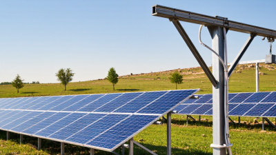
A solar pole mount system is an elevated structure that supports photovoltaic modules on one or more steel or aluminum poles. It raises panels above uneven ground, vegetation, snow, and occasional flooding. Its purpose is practical: improve solar exposure while reducing grading and ground disturbance.
According to IRENA’s Renewable Capacity Statistics 2024, global solar capacity reached about 1,419 GW by the end of 2023. That scale increases demand for adaptable mounting solutions. A field survey remains essential. Engineers should check soil strength, wind speed, frost depth, corrosion risk, and daily shading before selecting the pole diameter or foundation.
Pole-mounted arrays serve rural homes, farms, remote communications sites, water facilities, and small commercial projects. They can provide useful clearance around grazing areas or irregular land. In a real installation, installers may set concrete foundations beside a rocky fence line, then adjust tilt for seasonal sunlight. That detail matters. Incorrect spacing can create shadows and reduce output.
IEA PVPS reported that global photovoltaic deployment continued expanding sharply in 2023, with hundreds of gigawatts added worldwide, yet mounting quality still varies between regions. Single-axis tracking can increase energy yield, but it adds moving parts, maintenance, and wind exposure. Fixed systems are often simpler and more dependable. Still, that assumption can fail in high-snow or high-wind locations, where structural review and regular bolt inspections are necessary.
Top Solar Pole Mount Systems for Global Buyers
Key Components and Structural Designs of Pole-Mounted Solar Systems
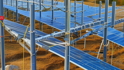
Pole-mounted solar systems rely on a small group of structural components. Steel or aluminum poles carry the main load. Rails support the modules, while clamps secure each panel against movement. Reinforced concrete foundations transfer wind and snow forces into the ground. Galvanized coatings help resist moisture, salt, and soil contact.
A reliable design also includes bearing assemblies, adjustable brackets, cable clips, and grounding connections. Fixed-tilt structures use fewer moving parts and usually require less maintenance. Tracking structures can improve energy capture, but motors, sensors, and drive shafts add weight and service needs. The choice depends on land conditions, climate, panel size, and access for maintenance.
Site measurements should guide every structural decision. Soil testing helps determine foundation depth and pole spacing. Wind exposure matters, especially on open farmland or elevated ground. Installers often inspect bolt tension, cable routing, and corrosion points after installation. Small errors can become expensive.
A neat drawing may still hide weak assumptions. Real sites contain stones, uneven grades, and drainage problems. Designers should leave practical adjustment space for these conditions. Thermal movement, shading between rows, and future module replacement also deserve attention. Safety factors should follow recognized engineering standards and local requirements, not guesswork. Reliable systems are engineered for the site, not copied from a catalog.
| Pole-Mount Design | Typical Array Capacity | Typical Tilt Configuration | Primary Structural Components | Foundation Approach | Best-Fit Applications | Key Design Considerations |
|---|---|---|---|---|---|---|
| Single-Pole Fixed-Tilt System | Usually 1–4 modules; approximately 0.4–2.0 kW per pole, depending on module size | Fixed angle, commonly selected near the site’s latitude or according to the project’s seasonal energy target | Steel or aluminum pole, top cap or mounting head, module rails, rail clamps, bracing, fasteners, cable clips and grounding hardware | Direct-buried or concrete-embedded pole; soil bearing capacity and frost depth must be verified locally | Remote loads, security lighting, agricultural equipment, small off-grid systems and residential installations with limited ground area | Simple and economical, but the pole, connection head and foundation must resist wind overturning, snow weight and corrosion exposure |
| Dual-Pole Fixed-Tilt System | Typically 4–12 modules; approximately 1.5–6.0 kW per mounting structure | Fixed south-facing or equator-facing orientation in the Northern or Southern Hemisphere, with a project-specific tilt angle | Two vertical posts, crossbeams, torque-resistant rails, diagonal bracing, adjustable tilt brackets, clamps and grounding connections | Two concrete footings, helical piles or driven piles, selected according to soil, access and local structural requirements | Medium-size off-grid arrays, farms, remote facilities and installations requiring greater stiffness than a single-pole structure | Improves load distribution and reduces torsion; post spacing should match module dimensions, rail spans and local wind calculations |
| Top-of-Pole Mount | Commonly 1–8 modules; approximately 0.4–4.0 kW per pole | Fixed tilt; some configurations use a manually adjustable seasonal angle | Vertical pole, top-of-pole adapter, module support frame, rails, clamps, bracing, anti-rotation hardware and grounding conductors | Concrete-embedded or driven pole; deeper embedment may be required for high wind exposure or weak soils | Small arrays, battery charging, telecom equipment, water pumping and sites where vegetation or animals could shade ground-level modules | Elevated modules can reduce shading and improve ground access, but increase wind exposure and maintenance-access requirements |
| Side-of-Pole Mount | Usually 1–2 modules; approximately 0.4–1.0 kW per pole | Fixed tilt with limited adjustment, depending on the bracket design | Pole saddle or side brackets, module rails, clamps, stainless or galvanized fasteners and bonding hardware | Uses an existing pole or a dedicated small pole; structural capacity and connection strength must be checked | Compact lighting, sensors, signage, small communications equipment and low-power remote monitoring systems | Fast to install and space-efficient, but generally supports less module area and may have lower energy yield if orientation is constrained |
| Multi-Module Elevated Pole Array | Approximately 2–16 modules; about 1.0–8.0 kW per structure, subject to wind and snow loads | Fixed tilt, usually configured for the project latitude, row spacing and annual energy objective | One or more heavy-duty poles, primary beams, secondary rails, diagonal braces, tilt joints, clamps, cable management and grounding network | Engineered concrete foundations, driven piles or helical piles; geotechnical information is recommended for larger arrays | Commercial off-grid systems, agricultural sites, microgrids and locations requiring clearance for vehicles, livestock or equipment | Requires detailed structural engineering for deflection, uplift, bolt connections, module load limits, access and installation logistics |
| Adjustable-Tilt Pole System | Usually 1–8 modules; approximately 0.4–4.0 kW per structure | Manual seasonal adjustment, often using multiple preset positions rather than continuous tracking | Pole, pivoting frame, angle-locking plates or struts, rails, clamps, anti-rotation components and grounding hardware | Concrete or driven foundation sized for the maximum tilted surface area and resulting wind moment | Seasonal-use sites, off-grid systems, high-latitude locations and projects where periodic manual maintenance is practical | May improve seasonal energy production, but moving joints require locking checks, corrosion protection and safe maintenance access |
Comparing solar pole mount systems starts with climate, not advertised output. IEA PVPS Trends 2024 reports over 1.6 terawatts of global photovoltaic capacity by the end of 2023. That scale makes site-specific engineering essential. In windy coastal areas, check design wind speed, gust exposure, foundation pull-out, and torsional stiffness. ASCE 7-22 provides wind-load methods, but local building codes still control. A narrow pole can look elegant. It may require deeper concrete.
Snowy regions need tilt, snow accumulation assumptions, and unbalanced-load checks. The National Renewable Energy Laboratory’s PVWatts documentation includes snow, temperature, and albedo as production inputs. Cold air can improve module efficiency, but heavy snow may block the array for weeks. In hot deserts, compare thermal expansion, ultraviolet resistance, and rear ventilation. Global Solar Atlas data can show strong irradiation, but dust still reduces real-world yield. A lower frame edge may develop a visible brown band.
Humid and marine sites require careful checks of galvanizing, drainage, dissimilar-metal contact, and fastener compatibility. IEC 61215 testing supports module durability, but it does not replace local corrosion assessment. Request stamped calculations, geotechnical data, and a maintenance plan. I would challenge my first choice. The cheapest steel can become expensive after one storm.
Installation, Safety, and Maintenance Requirements for Global Projects
A reliable pole mount begins with a site survey, not a product catalog. Check soil bearing capacity, frost depth, drainage, wind exposure, snow load, and seismic conditions. Measure twice. A structural engineer should verify foundation dimensions and steel thickness against local codes. The array must face its design direction without shading from trees, towers, or nearby buildings. Allow enough clearance for tools, cable bends, and safe access.
Installation crews need documented lifting procedures and stable temporary supports. Use corrosion-resistant fasteners suited to the local climate, especially near saltwater or industrial areas. Bond and ground metal components according to applicable electrical requirements. Protect cables inside UV-resistant conduit, and keep connectors above standing water. Workers should use fall protection, insulated tools, and lockout procedures where electrical hazards exist. Small shortcuts can become expensive failures.
Maintenance should include visual checks after severe wind, hail, flooding, or unusual vibration. Inspect posts for settlement, rust, cracking concrete, and loose hardware. Verify bolt torque with calibrated tools rather than relying on appearance. Clean drainage paths around foundations. Keep records. Inspection intervals may change with climate, soil movement, and project size. A yearly visit may be inadequate in harsh coastal regions. One overlooked detail remains common: installers may document the panels but forget the foundation. That gap deserves correction.
Top Solar Pole Mount Systems for Global Buyers
A reliable pole mount begins with material verification, not attractive product photos. Hot-dip galvanized steel suits harsh outdoor conditions, while marine-grade aluminum can reduce weight. Ask for coating thickness, alloy grades, weld procedures, and corrosion-test records. Stainless fasteners should match the environment, especially near saltwater. Structural calculations must reflect local wind, snow, seismic, soil, and module loads. A generic load table is rarely enough.
Certifications need careful checking. Request factory quality records, material certificates, installation drawings, and test reports from recognized laboratories. Relevant evidence may include structural compliance with local building codes, electrical bonding guidance, and quality systems such as ISO 9001. Certification claims can be vague. Verify the certificate number, issuing body, scope, and validity. I have seen documents that covered a component, not the complete mounting system.
Tips: Compare landed cost, not unit price. Include freight, customs duties, concrete, labor, tools, inspections, and replacement parts. Ask suppliers for a detailed bill of materials and a five-year maintenance estimate. A sample assembly or small pilot installation can reveal poor fit, missing bolts, or unclear instructions. Supplier selection should include production capacity, traceable inspections, engineering support, warranty terms, and response time. A low quote may still win, but my early estimates often missed soil work and local installation costs. That mistake deserves review before approving a large order.
Buyer checklist comparison: materials, certifications, cost impact, and supplier selection.
Reference material densities: aluminum approximately 2,700 kg/m³, carbon steel approximately 7,850 kg/m³, and stainless steel approximately 8,000 kg/m³. Actual system cost depends on design loads, coating requirements, quantity, logistics, and local installation conditions.