Choosing the best solar pole mount in 2026 requires more than comparing prices or glossy product images. A reliable mount must match the panel size, local wind exposure, soil conditions, and installation method. It should also support safe cable routing, stable grounding, and practical maintenance over many years.
This guide examines pole-mounted solar systems through an installer’s perspective. It considers galvanized steel, aluminum, corrosion resistance, adjustable tilt angles, foundation depth, and hardware quality. Manufacturer specifications matter, but field conditions matter just as much. A mount that performs well in dry, firm soil may struggle on a sloped site with loose ground. Small details can decide the outcome.
Real projects often reveal problems that product pages overlook. Bolts may be difficult to reach after assembly. Shadows can reduce winter production. Heavy snow may require stronger structural support than expected. Even an excellent design can fail when measurements are rushed. That deserves honest attention. No single solar pole mount suits every property, budget, or climate.
The comparisons ahead focus on durability, load capacity, installation effort, adjustability, and long-term value. They also consider warranty terms and the clarity of technical documentation. Independent verification remains important, especially for structural loads and electrical connections. Local professionals should confirm site-specific requirements before installation. A confident choice is not always the most expensive one. It is the mount that fits the site, the panels, and the people responsible for maintaining them.
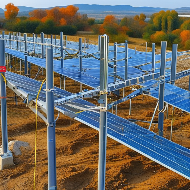
Solar pole mounts raise panels above ground, improving airflow, drainage, and access for maintenance. The best design depends on the site, not a universal product label. Top-of-pole mounts hold panels above a single post and suit open, sunny areas. Side-of-pole mounts attach lower on the structure, making installation easier beside fences or buildings. Multi-pole systems support larger arrays and reduce movement in exposed locations. Adjustable mounts can change panel angles, while tracking mounts follow sunlight but require more maintenance and stronger foundations.
For 2026 selection, check wind speed, snow weight, soil strength, corrosion risk, and local electrical requirements. A qualified installer should verify foundation depth and structural loads before purchasing. Bifacial panels may benefit from higher clearance and reflective ground surfaces. Aluminum and galvanized steel can resist weather, but surface protection still needs inspection. In my site reviews, poor drainage has caused more trouble than expected. That detail is easy to miss. Avoid choosing by panel capacity alone; fasteners, tilt adjustment, cable routing, and service access also affect long-term performance. Published load data and clear installation instructions improve reliability.
Tips: Measure the site during different seasons. Observe shadows, standing water, and prevailing wind. Ask for stamped structural calculations when conditions are severe. Leave enough space for cleaning and replacement. A slightly simpler mount may outperform a complex system when local maintenance skills are limited. Recheck assumptions before installation.
What Is the Best Solar Pole Mount in 2026?
The best solar pole mount depends on your energy target, land conditions, and maintenance capacity. A fixed mount points panels in one direction and keeps moving parts out of the system. It usually costs less, handles strong weather well, and suits remote properties with limited service access. However, its yearly output may drop when the sun moves far from the panel’s ideal angle.
An adjustable mount offers a practical middle ground. You can change its tilt for summer and winter, improving sunlight capture without motors or complex controls. A technician can usually inspect the frame, bolts, and foundation with basic tools. Still, seasonal adjustments require planning. Missed changes can reduce the expected benefit.
Tracker designs follow the sun across the sky. NREL analyses commonly report energy gains of about 15–25% compared with fixed systems, depending on location, shading, weather, and tracker design. That gain can matter where land is limited or electricity demand peaks during bright afternoons. Trackers also need motors, sensors, stronger foundations, and routine inspections. More output is not automatically better. Dust, snow, wind, and a failed drive system can erase part of the advantage. A site with heavy snowfall may favor a simpler adjustable structure, even when simulations predict higher tracker production. My own design review would include hourly shading data, local wind loads, soil testing, and realistic maintenance access. The perfect mount rarely exists.
Comparison assumes a ground-mounted photovoltaic array in a suitable solar resource. Energy-gain figures are indicative ranges relative to a fixed, optimally tilted array; actual results depend on location, shading, array geometry, weather, and system controls.
| Evaluation Dimension | Fixed Pole Mount | Adjustable-Tilt Pole Mount | Single-Axis Tracking Pole Mount |
|---|---|---|---|
| Typical movement | No movement after installation; modules remain at one selected tilt and azimuth. | Manual seasonal or periodic tilt adjustment; normally no daily movement. | Motorized daily rotation, typically following the sun from east to west around one axis. |
| Indicative annual energy gain | Baseline: 0% | Approximately 2–10% Compared with a fixed array at a non-optimal or compromise tilt. |
Approximately 15–25% Commonly cited by NREL for suitable utility-scale conditions compared with fixed-tilt systems. |
| Best application | Small residential, agricultural, remote, or off-grid systems where simplicity is the priority. | Sites where owners can access the array safely and want modest production improvement without motors. | Large, unobstructed sites seeking higher annual yield and improved morning-to-afternoon production. |
| Installation complexity | Low Few moving parts and straightforward structural installation. |
Low to medium Requires a locking mechanism and a safe adjustment procedure. |
High Requires drives, controls, mechanical clearances, wiring, and commissioning. |
| Operating and maintenance needs | Minimal Routine inspection, fastener checks, vegetation control, and module cleaning where needed. |
Low Periodic inspection plus manual seasonal adjustments. |
Medium to high Includes drive-system inspection, control checks, lubrication or component replacement as specified by the equipment design. |
| Wind and weather considerations | Generally easier to engineer because the array has a fixed aerodynamic position. | Requires structural checks for each permitted tilt position. | Requires wind-stow logic, stronger controls, and structural analysis for operating and stowed positions. |
| Land-use efficiency | High Row spacing can be relatively compact, subject to shading and access requirements. |
High Similar land planning to fixed systems when adjustments are limited. |
Medium More spacing may be needed to limit row-to-row shading and allow tracking movement. |
| Electrical requirements | Standard photovoltaic wiring and inverter equipment. | Standard photovoltaic wiring; no tracking power circuit is normally required. | Additional low-voltage power, control wiring, sensors, or communications may be required. |
| Performance during cloudy conditions | Often similar to other designs when diffuse irradiance dominates. | Often similar to other designs during heavily overcast periods. | Tracking advantage can decrease when direct-beam sunlight is limited by clouds or haze. |
| Relative cost profile | Lowest Usually the least expensive option to install and operate. |
Low to medium Higher hardware and labor cost than fixed mounting, but no motorized drive system. |
Highest Higher structural, controls, installation, and long-term service requirements. |
| Recommended choice | Choose when reliability, low maintenance, limited space, or a small system matters most. | Choose when moderate energy improvement is valuable and manual access is practical. | Choose when the site is open, direct sunlight is strong, the project is large enough to justify added complexity, and a 15–25% gain can improve project economics. |
Technical note: The 15–25% tracker-gain range is a planning benchmark associated with NREL analyses of single-axis tracking under suitable conditions, not a guaranteed result for every site. Final selection should use site-specific irradiance, wind, soil, shading, row-spacing, energy-price, and lifecycle-cost analyses.
What Is the Best Solar Pole Mount in 2026?
The best solar pole mount is not defined by steel thickness alone. Its entire load path must be verified. ASCE 7-22 provides a framework for evaluating wind and snow effects. Designers should confirm site wind speed, risk category, exposure, topography, and applicable local amendments. A coastal field and a sheltered suburban lot cannot use identical assumptions. They should not.
Solar panel area, tilt, height, and spacing directly affect wind pressure and overturning. Check uplift, lateral shear, bending, and axial compression at every pole. Do not stop at the pole. Base plates, bolts, welds, sleeves, and concrete foundations must resist combined actions. Snow design should include ground snow load, exposure, thermal conditions, importance factors, and unbalanced accumulation where applicable. Small changes matter.
Reliable verification requires site-specific calculations prepared by a qualified structural engineer. The design record should show load combinations, connection capacities, soil assumptions, and foundation dimensions. Field inspection should confirm embedment depth, concrete strength, bolt grade, and actual panel tilt. Local approval requirements may alter how ASCE 7-22 is applied. One uncomfortable lesson is that “best” comparisons often ignore construction tolerances and corrosion. A spreadsheet can still hide a weak assumption. Revisiting the calculations is sensible when the array becomes taller, heavier, or installed in softer soil than originally expected.
Verify Pole Loads Against ASCE 7-22 Wind and Snow Requirements
This reference chart compares calculated velocity pressure for three wind-speed examples with representative ground snow loads. Wind pressure uses the ASCE 7-22 velocity-pressure relationship qz = 0.00256KzKztKdV² with Kz = 0.85, Kzt = 1.0, and Kd = 0.85. Actual pole-mount design must use the project location, exposure category, topographic effects, risk category, snow conditions, tributary area, and applicable load combinations.
Reference values are shown in pounds per square foot (psf) and are not a substitute for a site-specific structural analysis.
Bifacial compatibility should guide your pole-mount decision in 2026. NREL commonly references a practical bifacial gain of about 5–15% under suitable conditions. That range is useful, but it is not a promise. A white gravel surface may reflect more light than dark soil. Snow can increase rear-side output, while wet ground may change readings again.
Look for a mount that leaves clear space behind the panels. Rear shading from poles, rails, clamps, and cables can reduce bifacial performance. Taller supports usually improve light access, but they may face stronger wind loads. Adjustable tilt can help match seasonal sun angles, although moving hardware creates another maintenance task. The best design balances rear exposure, structural stability, and local weather data.
A simple site check helps. Measure the ground reflectivity, note nearby obstructions, and inspect shadows at morning and afternoon. Keep the panel’s rear surface clean and avoid placing dark equipment directly below it. My first estimate would use the lower 5% gain, not the headline 15%. That feels cautious. Actual results may disappoint if spacing is tight or the ground stays shaded. Compare front and rear irradiance with reliable sensors before approving the final layout. Small installation details matter more than optimistic calculations.
What Is the Best Solar Pole Mount in 2026?
Rank 2026 mounts by LCOE, durability, and IEC 61215/61730 compliance. The lowest LCOE usually comes from a fixed, hot-dip galvanized steel pole mount. It uses fewer moving parts and needs less maintenance. Installation is also predictable on open, level ground. However, steel can corrode where water collects, especially around drilled holes and fasteners. Inspect those points annually.
Adjustable steel mounts rank second when seasonal tilt improves energy production. Their higher labor and hardware costs may still reduce LCOE in high-latitude regions. Aluminum mounts rank third for coastal sites because they resist surface corrosion and remain lightweight. They can cost more, though. Mixed-metal connections require careful isolation. Small mistakes can trigger galvanic corrosion.
IEC 61215 and IEC 61730 primarily qualify and certify photovoltaic modules, not pole structures. A credible mount assessment should verify module compatibility, load calculations, torque records, and structural testing. Check wind uplift, snow pressure, soil pullout, and drainage details. Look for documentation, not marketing language. A mount can support certified modules without being IEC-certified itself.
Real projects are less tidy than spreadsheets. One site may favor a cheaper fixed mount because labor is available locally. Another may justify adjustment hardware after shading analysis. Soil conditions can change the ranking completely. I would request a corrosion warranty, engineering drawings, and replacement-part availability before comparing headline prices.